Ieee 39 Bus System
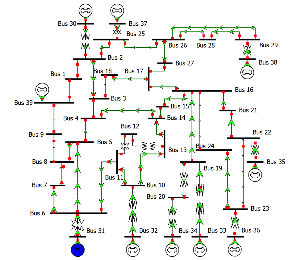
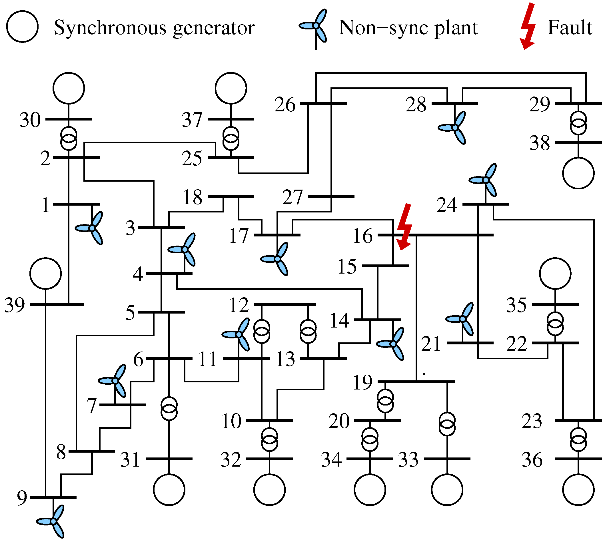
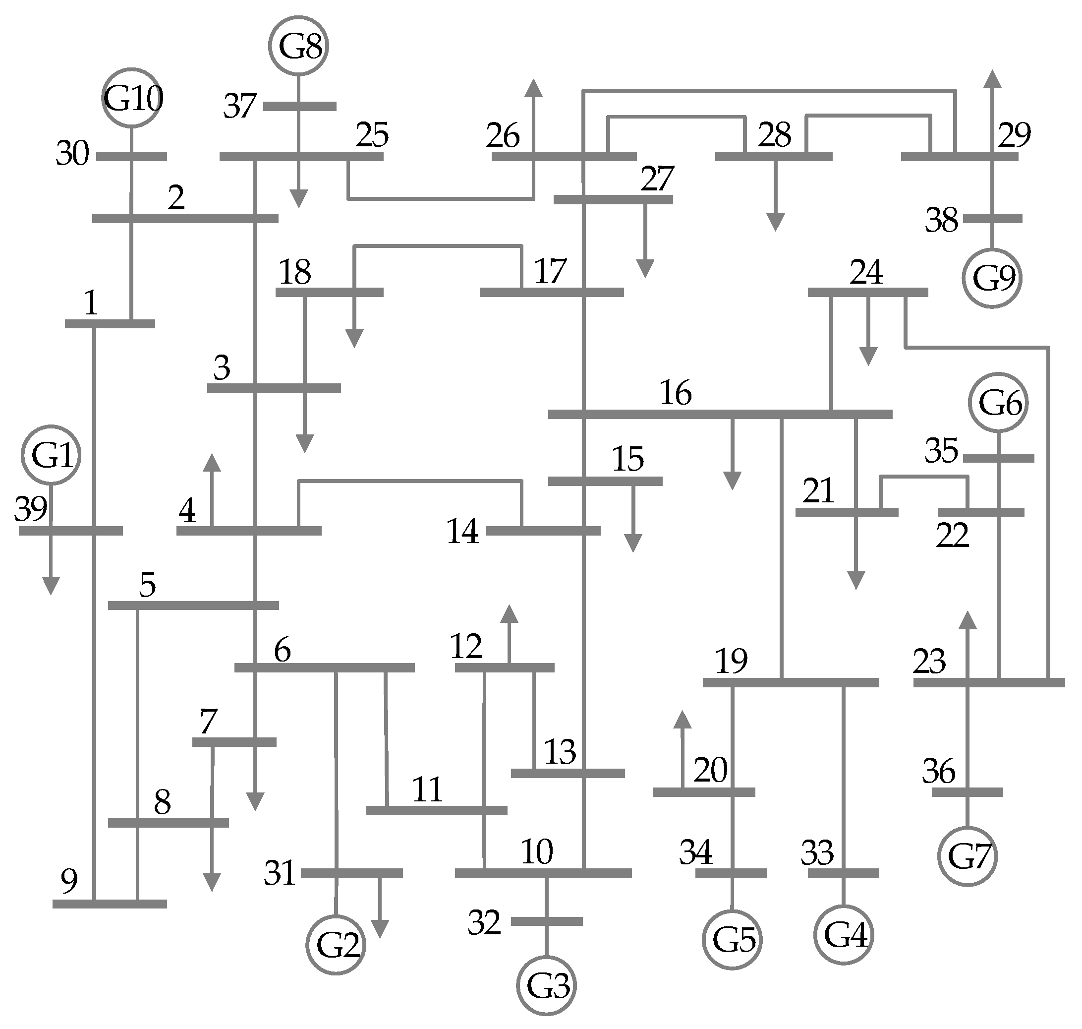
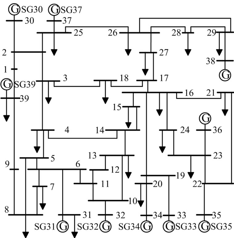
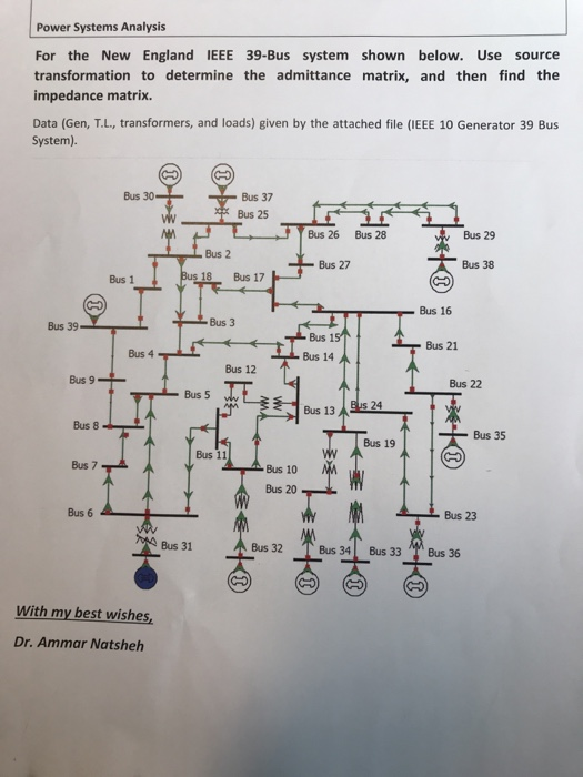
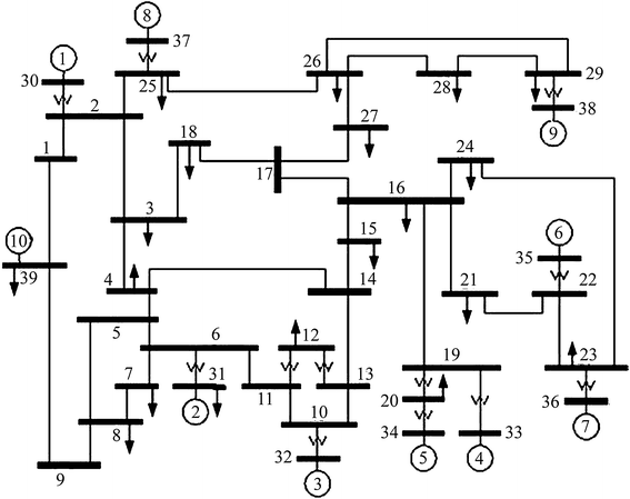
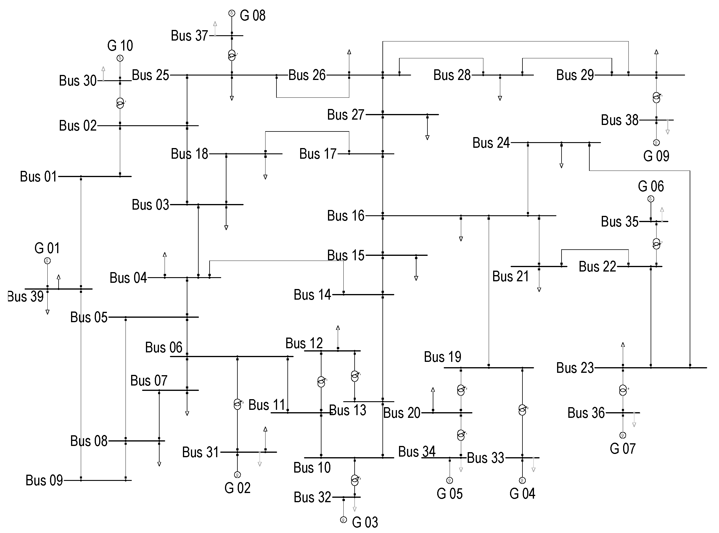
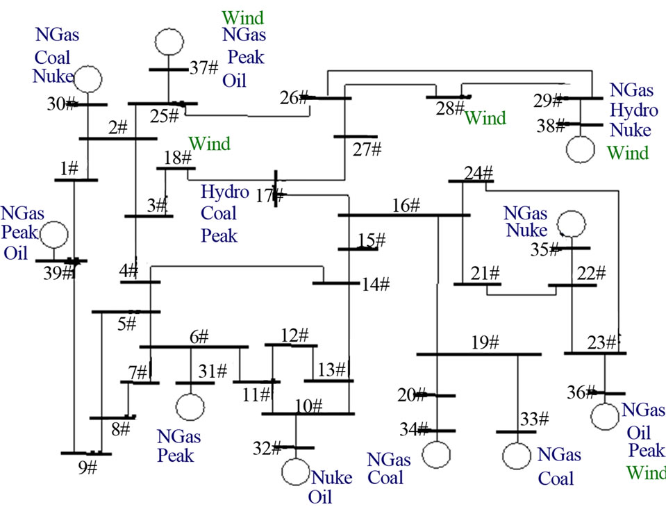
Ieee 39 bus system. Single line diagram of the 39 Bus New England System tem US. This test case consists of 15. In the paper the standard IEEE 10-generator 39-bus test system is simulated offline and also in real-time using an educational real-time simulator called miniature full spectrum simulator Mini-FSS.
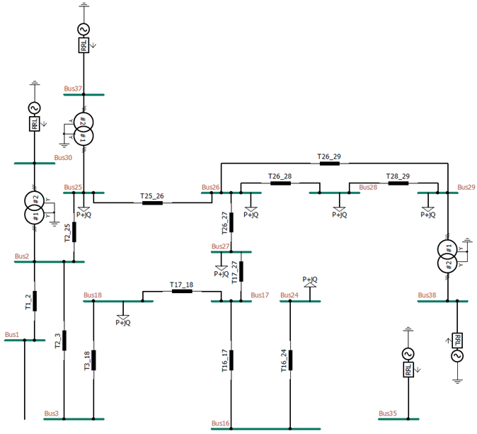
In a power system the interactions between one another among the various generators their excitation systems and their automatic voltage regulators lead to low-frequency. Figure 1 depicts part of the PSCAD model of IEEE 39-bus system. The help document of this component is given in Appendix.
The values of various parameters is shown in Appendix 2Firstly load flow analysis is performed on the system using Mipower software and its results are shown along with the system in Appendix 1. Athay et al1 and are published in a book titled Energy Function Analysis for Power System Stability2. Technical Specification - IEEE 39 bus.
The example comes with a technical write up that describes the work done and the data used. This case is used to study simultaneous damping of local and inter-are modes in a. The model is loosely based on the IEEE 39-bus system presented by T.
14 Generators The 39-bus system is composed by generators 10 and all of them are represented by a synchronous machine SM. George--George Wai Software Support Development. So we just put a small value 1 kW here and use model 3 to regulate the bus.
This case is used to study simultaneous damping of local and inter-are modes in a system wit ha highly symmetrical. Generator 1 represents the aggregation of a large number of generators. A hardcopy data was provided by Iraj Dabbagchi of AEP and entered in IEEE Common Data Format by Rich Christie at the University of Washington in August 1993.
The IEEE 39 bus system is well known as 10-machine New-England Power System. And Canadian and is therefore directly connected at the 345 kV level.
Data taken from 1 with.
The help document of this component is given in Appendix. The IEEE 39 bus system is well known as 10-machine New-England Power System. The MATLAB simulation for IEEE 39-bus System is demonstrated by JKD Power and Energy solutions The MATLAB model for download is provided in the link given be. Data taken from 1 with. Single line diagram of the 39 Bus New England System tem US. New GeneratorB6 Bus1B35 kV 220 kW650000 Model3 Vpu10493. Figure 1 depicts part of the PSCAD model of IEEE 39-bus system. Comparison of Series and Shunt FACTS to Improve the Performance of Power System with Wind Penetration Wind generation. Athay et al1 and are published in a book titled Energy Function Analysis for Power System Stability2.
The authors of the SimPowerSystems implementation of this benchmark are Ali Moeini and Innocent Kamwa from IREQ Hydro-Québec research institute. The IEEE 39-bus system analyzed in this report is commonly known as the 10-machine New-England Power SystemThis systems parameters are specified in a paper by T. This test case consists of 15. The values of various parameters is shown in Appendix 2Firstly load flow analysis is performed on the system using Mipower software and its results are shown along with the system in Appendix 1. Data taken from 1 with. The authors of the SimPowerSystems implementation of this benchmark are Ali Moeini and Innocent Kamwa from IREQ Hydro-Québec research institute. Single line diagram of the 39 Bus New England System tem US.













Post a Comment for "Ieee 39 Bus System"